morse.sensors package
Submodules
morse.sensors.accelerometer module
-
class
Accelerometer(obj, parent=None)[source]¶ Bases:
morse.core.sensor.SensorThis sensor emulates an Accelerometer/Podometer, measuring the distance that a robot has moved, the current speed and current acceleration. Measurements are done for the 3 axes (X, Y, Z) for velocity and acceleration. The values for velocity and acceleration are measured at each tic of the Game Engine, measuring the difference in distance from the previous tic, and the estimated time between tics (60 tics per second is the default in Blender).
morse.sensors.airspeed module
-
class
Airspeed(obj, parent=None)[source]¶ Bases:
morse.core.sensor.SensorSensor to compute Airspeed
The current implementation is only correct for speed < 1Mach
morse.sensors.armature_pose module
-
class
ArmaturePose(obj, parent=None)[source]¶ Bases:
morse.core.sensor.SensorThe sensor streams the joint state (ie, the rotation or translation value of each joint belonging to the armature) of its parent armature.
Note
This sensor must be added as a child of the armature you want to sense. See the Examples section below for an example.
robot = ATRV()

arm = KukaLWR()
robot.append(arm)
arm.translate(z=0.9)

arm_pose = ArmaturePose()
# the sensor is appended to the armature, *not* to the robot
arm.append(arm_pose)
This component only allows to read armature configuration. To change the armature pose, you need an armature actuator.
Important
To be valid, special care must be given when creating armatures. If you want to add new one, please carefully read the armature creation documentation.
Note
The data structure on datastream exported by the armature sensor depends on the armature. It is a dictionary of pair (joint name, joint value). Joint values are either radians (for revolute joints) or meters (for prismatic joints)
Sees: armature actuator Noautoexample: -
default_action()[source]¶ Get the x, y, z, yaw, pitch and roll of the armature, and the rotation angle for each of the segments.
-
get_joint(joint)[source]¶ Returns the value of a given joint, either: - its absolute rotation in radian along its rotation axis, or - it absolute translation in meters along its translation axis.
Throws an exception if the joint does not exist.
Parameters: joint – the name of the joint in the armature.
-
get_joints()[source]¶ Returns the list of joints of the armature.
Returns: the (ordered) list of joints in the armature, from root to tip.
-
morse.sensors.attitude module
-
class
Attitude(obj, parent=None)[source]¶ Bases:
morse.core.sensor.SensorThis sensor is an high-level sensor, returning the attitude of the sensor (i.e. angles and angular velocities). It can be seen as the integration of an IMU, or a couple gyroscope/gyrometer.
If the robot has a physics controller, the velocities are directly read from its property
localAngularVelocity. Otherwise the velocities are calculated by simple differentiation. The measurements are given in the sensor coordinate system.
morse.sensors.barometer module
-
class
Barometer(obj, parent=None)[source]¶ Bases:
morse.core.sensor.SensorSensor to compute the atmopsheric pressure, using the ISA model:
- https://en.wikipedia.org/wiki/International_Standard_Atmosphere
- http://en.wikipedia.org/wiki/Atmospheric_pressure
The current implementation is only correct in the Troposphere, i.e. for an altitude less than 11000m
morse.sensors.battery module
-
class
Battery(obj, parent=None)[source]¶ Bases:
morse.core.sensor.SensorThis sensor emulates the remaining charge of a battery on the robot. It is meant to be used only as an informative measure, to be taken in consideration by the planning algorithms. It does not prevent the robot from working.
The charge of the battery decreases with time, using a predefined Discharge rate specified as a property of the Blender object. This rate is independent of the actions performed by the robot, and only dependant on the time elapsed since the beginning of the simulation.
If the battery enters in a Charging zone, the battery will gradually recharge.
morse.sensors.camera module
-
class
Camera(obj, parent=None)[source]¶ Bases:
morse.core.sensor.SensorA generic camera class, which is expected to be used as a base class for real camera. Concrete instantiation are currently:
Note
The cameras make use of Blender’s bge.texture module, which requires a graphic card capable of GLSL shading. Also, the 3D view window in Blender must be set to draw Textured objects.
Note
The streaming of data from this sensor can be toggled off and on by pressing the SPACE key during the simulation. This will affect all the video cameras on the scene.
Toggling off the cameras can help make the simulation run faster, specially when there are several cameras. However, the lack of data on the stream may cause problems to some middlewares.
Note
The cam_focal and cam_fov properties are linked together. Blender automatically computes one when setting the other. Therefore when setting cam_fov to something other than None, the cam_focal parameter is ignored.
Warning
Contrary to most of objects in Morse, the X axis of the camera is not “in front” of the camera. Here, Morse follows the “standard convention for camera”, i.e. X and Y are in the image plane, and Z is in the depth axis of the camera.
-
image_data
-
morse.sensors.clock module
-
class
Clock(obj, parent=None)[source]¶ Bases:
morse.core.sensor.SensorThis sensor returns the current time, measured by the robot (in s).
morse.sensors.collision module
-
class
Collision(obj, parent=None)[source]¶ Bases:
morse.core.sensor.SensorSensor to detect objects colliding with the current object.
It allows to select which objects are sensed for collision by setting the property
only_objects_with_property(see the Examples section for an example).This sensor is a wrapper around Blender’s own Collision sensor.
from morse.builder import *

# adds a default robot (the MORSE mascott!)
robot = Morsy()

# create and add a Collision sensor
collision = Collision()

# place it on the front side of the robot
collision.translate(0.43,0,0.3)

# only detect collision with objects which have the property 'Object'.
# see the documentation of `Passive Objects` for details:
# http://www.openrobots.org/morse/doc/latest/user/others/passive_objects.html
collision.properties(only_objects_with_property="Object")

robot.append(collision)
# for this example, we use the socket interface
collision.add_interface("socket")

# we also add a keyboard actuator to be able to move
# around our robot to test collisions
keyboard = Keyboard()
robot.append(keyboard)

# the 'sandbox' test environment offers plenty of objects to test
# collisions. These objects have all the property 'Object' already set.
env = Environment('sandbox')

# Copy this code to a script, and run it with `morse run <script>`!
# This is a sample *client* code that uses pymorse to count the
# collisions. Copy this code to a different script, start it with
# `python3 <script>`, and move the robot in the simulator with the
# arrow keys: when you collide with an object, it is printed on the
# console.

import pymorse

nb_collisions = 0

def counter(data):
    global nb_collisions

    if data["collision"]:
        nb_collisions += 1
        print("Collision with %s! In total, %d collisions occured" % (data["objects"], nb_collisions))


with pymorse.Morse() as morse:

    morse.robot.collision.subscribe(counter)

    print("Press ctrl+C to stop")
    while True:
        morse.sleep(10)
Noautoexample:
morse.sensors.compound module
-
class
CompoundSensor(obj, parent=None)[source]¶ Bases:
morse.core.sensor.SensorThis special sensor is constructed by passing a list of other sensors, and creates a new datastream from the concatenation of other sensors’ local_data.
More accurately, it streams a dictionary of {<sensor name>: <sensor local_data>}.
Note that services exposed by original sensors are not exposed by the compound sensor.
Noautoexample:
morse.sensors.depth_camera module
-
class
DepthCamera(obj, parent=None)[source]¶ Bases:
morse.sensors.depth_camera.AbstractDepthCameraThis sensor generates a 3D point cloud from the camera perspective.
See also Generic Camera for generic informations about Morse cameras.
-
class
DepthCameraRotationZ(obj, parent=None)[source]¶ Bases:
morse.sensors.depth_camera.DepthCameraUsed for Velodyne sensor
-
class
DepthVideoCamera(obj, parent=None)[source]¶ Bases:
morse.sensors.depth_camera.AbstractDepthCameraThis sensor generates a Depth ‘image’ from the camera perspective.
“Depth images are published as sensor_msgs/Image encoded as 32-bit float. Each pixel is a depth (along the camera Z axis) in meters.” [ROS Enhancement Proposal 118](http://ros.org/reps/rep-0118.html) on Depth Images.
If you are looking for PointCloud data, you can use external tools like [depth_image_proc](http://ros.org/wiki/depth_image_proc) which will use the
intrinsic_matrixand theimageto generate it, or eventually theXYZCameraClassin this module.
-
class
RawImage(obj, parent=None)[source]¶ Bases:
morse.sensors.depth_camera.AbstractDepthCameraThis sensor gets raw Z-Buffer from the camera perspective.
See also Generic Camera for generic informations about Morse cameras.
morse.sensors.depth_camera_aggregator module
-
class
DepthCameraAggregator(obj, parent=None)[source]¶ Bases:
morse.core.sensor.Sensor-
capture(callback, *param)¶ The service takes an integer an argument and dispatch the call to all its individual cameras. The service ends when each camera has terminated its work.
Parameters: n – the number of call to each individual camera
-
interrupt()[source]¶ This method is automatically invoked by the component when a service is interrupted, basically to notify to the client that the task has been interrupted.
It can be overriden in each component to provide a true interrupt, for exemple resseting the speed command to 0.0.
If you override it, do not forget to call
self.completedwithstatus.PREEMPTED.
-
morse.sensors.gps module
-
class
ExtendedGPS(obj, parent=None)[source]¶ Bases:
morse.sensors.gps.RawGPSAdditional information to fit a standard GPS-sentence
-
class
GPS(obj, parent=None)[source]¶ Bases:
morse.core.sensor.SensorA GPS sensor which returns the position either in Blender or Geodetic coordinates.
This sensor always provides perfect data on the levels “raw” and “extended”. To obtain more realistic readings, it is recommended to add modifiers.
- Noise modifier: Adds random Gaussian noise to the data
coordinates in Blender: x -> east and y -> north
The “heading” is Clockwise (mathematically negative).
Warning
To work properly in “raw” and “extented” mode, you need to configure the following variables at the environment level:
- longitude in degrees (double) of Blender origin
- latitude in degrees (double) of Blender origin
- altitude in m of the Blender origin
- optionnaly angle_against_north in degrees is the angle between geographic north and the blender X axis. angle_against_north is positive when the blender X-axis is east of true north, and negative when it is to the west.
To be able to simulate a GPS-sensor P (the Blender origin) must be defined in the properties in Geodetic coordinates (longitude, latitude, altitude). For the transformation [Psas] the coordinates must be in decimal degrees (no North, minutes, etc.). The result is a point x_0 in the
ECEF-rcoordinates.For this conversion x_0 is the base. A point x_e is given in the
ECEF-rcoordinates and the goal is to get x_t (= x_e in theLTP-coordinates).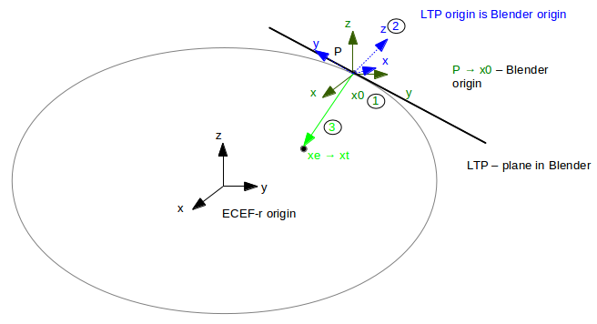
1. Transform P (Blender origin, geodetic coordinates (stored in the properties)) into x0 (geocentric (
ECEF-r) coordinates)2. Calculate R_{te}[1] with longitude, latitude and altitude; matrix is the rotation part of the transformation
- Transform x_e into x_t with x_t = R_{te} * (x_e-x_0)
Known: P in Geodetic coordinates (→ x_0 in
ECEF-r) and x_t inLTP-coordinatesGoal: x_e (= x_t in
ECEF-rcoordinates)Based on the transformation described above the transformation is calculated with the transposed matrix R_{te}: x_e = x_0 + (R_{te})' * x_t [Psas]
The last transformation is from
ECEF-rcoordinates into Geodetic coordinates. This transformation is calculated with the Vermeille’s method [FoIz]. The result is the point x_e in “GPS-coordinates” in radians.“3.4 Vermeille’s Method(2002)” in “Comparative Analysis of the Performance of Iterative and Non-iterative Solutions to the Cartesian to Geodetic Coordinate Transformation”, Hok Sum Fok and H. Bâki Iz, http://www.lsgi.polyu.edu.hk/staff/zl.li/Vol_5_2/09-baki-3.pdf“Conversion of Geodetic coordinates to the Local Tangent Plane”, Version 2.01, http://psas.pdx.edu/CoordinateSystem/Latitude_to_LocalTangent.pdf
-
class
RawGPS(obj, parent=None)[source]¶ Bases:
morse.sensors.gps.GPSThis sensor emulates a GPS, providing the exact coordinates in the Blender scene. The coordinates provided by the GPS are with respect to the origin of the Blender coordinate reference.
-
default_action()[source]¶ Calculates speed and GPS-position
Configurations are the GPS-values for the Blenderorigin Transforms point from LTP to Geodetic coordinates
Refer to: - Conversion of Geodetic coordinates to the Local Tangent Plane,
- Comparative Analysis of the Performance of Iterative and Non-iterative Solutions to the Cartesian to Geodetic Coordinate Transformation, Hok Sum Fok and H. Bâki Iz, http://www.lsgi.polyu.edu.hk/staff/zl.li/Vol_5_2/09-baki-3.pdf
-
morse.sensors.gyroscope module
-
class
Gyroscope(obj, parent=None)[source]¶ Bases:
morse.core.sensor.SensorThis sensor emulates a Gyroscope, providing the yaw, pitch and roll angles of the sensor object with respect to the Blender world reference axes.
Angles are given in radians.
morse.sensors.human_posture module
-
class
HumanPosture(obj, parent=None)[source]¶ Bases:
morse.core.sensor.SensorThis sensor collects the positions of the bones in the human armature for the file
$MORSE_ROOT/data/robots/human.blend.It stores the position and orientation of the general armature object, as well as the local rotation of each individual bone. The rotation angles are given in radians.
This sensor will only work for the
human.blendmodel, as it uses a specific naming convention for each of the bones.You can also check to general documentation of the human component.

morse.sensors.imu module
-
class
IMU(obj, parent=None)[source]¶ Bases:
morse.core.sensor.SensorThis sensor emulates an Inertial Measurement Unit (IMU), measuring the angular velocity and linear acceleration including acceleration due to gravity. For the magnetic field part, refer to the documentation of ./magnetometer.
If the robot has a physics controller, the velocities are directly read from it’s properties
localAngularVelocityandworldLinearVelocity. Otherwise the velocities are calculated by simple differentiation. Linear acceleration is always computed by differentiation of the linear velocity. The measurements are given in the IMU coordinate system, so the location and rotation of the IMU with respect to the robot is taken into account.-
default_action()[source]¶ Get the speed and acceleration of the robot and transform it into the imu frame
-
morse.sensors.laserscanner module
-
class
LaserScanner(obj, parent=None)[source]¶ Bases:
morse.core.sensor.SensorThis is a generic sensor class used to emulate laser range scanners, including a variety of SICK and Hokuyo sensors.
This sensor works by generating a series of rays in predefined directions, and then computing whether any active object is found within a certain distance from the origin of the sensor.
The resolution and detection range can be completely configured using the MORSE Builder API. This will generate a flat mesh with a semi-circular shape, where its vertices represent the directions in which the rays of the sensor are cast. It is also possible to create a sensor with multiple scan layers, such as the SICK LD-MRS. This is configured using the parameters specified below.
Note
Objects in the scene with the No collision setting in their Game properties will not be detected by this sensor
SICK LMS500
SICK LD-MRS

Hokuyo
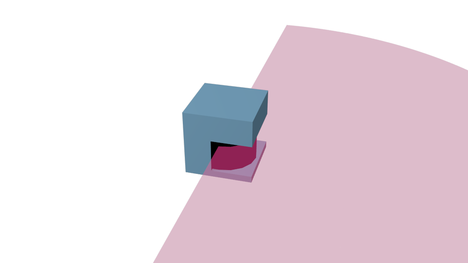
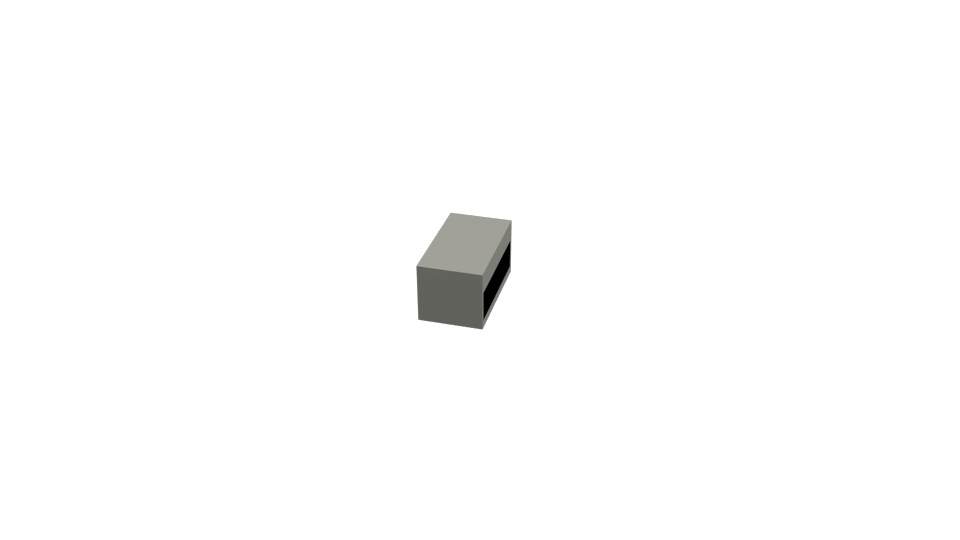
Remission “is the reflection or scattering of light by a material.” (http://en.wikipedia.org/wiki/Remission_%28spectroscopy%29)
The level “rssi” adds a list of remission values to the LaserScanner. If a ray during the scan hits an object the rssi-value is the specular intenisty of the object’s material; If it does not hit an object with a material the remission value is set to 0.
The intensity of the material can be changed in Blender (Property -> Material -> Specular -> Intensity). The important options are highlighted in the first image.
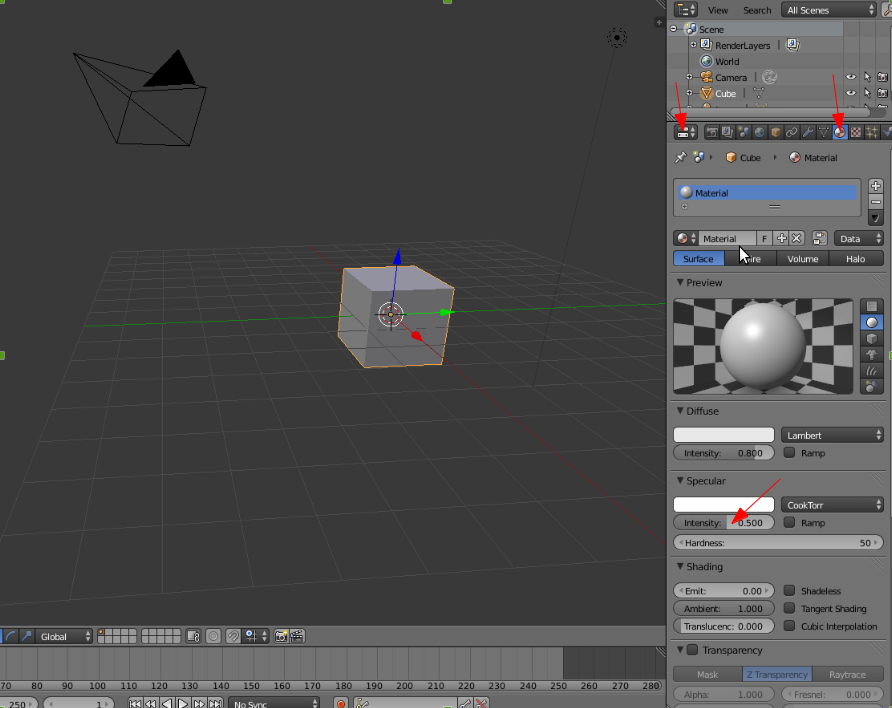
Specular intensity of a material in Blender
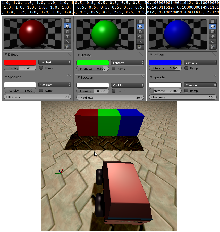
Example of the LaserScanner with remission values
In the second image the sensor is illustrated. Above every box the material properties and a corresponding excerpt from the socket stream is displayed.
Note
The remission values are not comparable to any physical remission value and are not calculated. They are just based on a property of a visual effect.
The number and direction of the rays emitted by the sensor is determined by the vertices of a semi-circle mesh parented to the sensor. The sensor will cast rays from the center of the sensor in the direction of each of the vertices in the semi-circle.
Three preconfigured scanners are available: a SICK LMS500 laser scanner, a Hokuyo and a SICK LD-MRS. The example below shows how to add them in a simulation:
from morse.builder import *

# Append a sick laser
sick = Sick() # range: 30m, field: 180deg, 180 sample points

hokuyo = Hokuyo() # range: 30m, field: 270deg, 1080 sample points

sick_ld_mrs = SickLDMRS() # range: 30m, field 100deg, 4 layers, 400 points per layer
All these default parameters can be changed i(cf Configuration parameters below). An example of how to change the arc object using the Builder API is show below:
from morse.builder import *

# Append a sick laser
sick = Sick()
sick.properties(resolution = 5)
sick.properties(scan_window = 90)
sick.properties(laser_range = 5.0)
Note
In some special cases (like multi-robot setups), you may need to additionally call
sick.create_sick_arc()after setting your scanner properties.The ray will be created from (-window/2) to (+window/2). So the
range_listwill contain the range clockwise.Another example for the SICK LD-MRS:
from morse.builder import *

sick = SickLDMRS()
sick.properties(Visible_arc = True)
sick.properties(resolution = 1.0)
sick.properties(scan_window = 100)
sick.properties(laser_range = 50.0)
sick.properties(layers = 4)
sick.properties(layer_separation = 0.8)
sick.properties(layer_offset = 0.25)
As with any other component, it is possible to adjust the refresh frequency of the sensor, after it has been defined in the builder script. For example, to set the frequency to 1 Hz:
sick.frequency(1.0)
-
class
LaserScannerRotationZ(obj, parent=None)[source]¶ Bases:
morse.sensors.laserscanner.LaserScannerUsed for Velodyne sensor
-
class
RSSILaserScanner(obj, parent=None)[source]¶ Bases:
morse.sensors.laserscanner.LaserScanner-
default_action()[source]¶ Do ray tracing from the SICK object using a semicircle
Generates a list of lists, with the points located. Also deforms the geometry of the arc associated to the SICK, as a way to display the results obtained.
-
getRSSIValue(target)[source]¶ IMPORTANT: To get the material property a workaround is needed. The material from the targets is KX_BlenderMaterial (and not KX_PolygonMaterial). So the properties are not accessible. Workaround: Get material name of the GameObject and then use the method bpymorse.get_material(name). Material name must be parsed because of the prefix ‘MA’ in Blender; before the name is used to get the material properties.
-
morse.sensors.magnetometer module
-
class
Magnetometer(obj, parent=None)[source]¶ Bases:
morse.core.sensor.SensorThis sensor computes the magnetic field vector, at the sensor position. It relies on the WMM2015 model, available at NOAA.
Warning
For proper computation, the sensor needs a real position on Earth, and so the following properties should be added at the environment level:
- longitude in degrees (double) of Blender origin
- latitude in degrees (double) of Blender origin
- altitude in m of the Blender origin
- optionnaly angle_against_north in degrees is the angle between geographic north and the blender X axis. angle_against_north is positive when the blender X-axis is east of true north, and negative when it is to the west.
morse.sensors.odometry module
-
class
Odometry(obj, parent=None)[source]¶ Bases:
morse.core.sensor.SensorThis sensor produces relative displacement with respect to the position and rotation in the previous Blender tick. It can compute too the position of the robot with respect to its original position, and the associated speed.
The angles for yaw, pitch and roll are given in radians.
Note
This sensor always provides perfect data. To obtain more realistic readings, it is recommended to add modifiers.
- Noise modifier: Adds random Gaussian noise to the data
- Odometry Noise modifier: Simulate scale factor error and gyroscope drift
morse.sensors.pose module
-
class
Pose(obj, parent=None)[source]¶ Bases:
morse.core.sensor.SensorThis sensor returns the full pose of the sensor, i.e. both translation and rotation with respect to the Blender world frame.
morse.sensors.proximity module
-
class
Proximity(obj, parent=None)[source]¶ Bases:
morse.core.sensor.SensorThis sensor can be used to determine which other objects are within a certain radius of the sensor. It performs its test based only on distance. The type of tracked objects can be specified using the Track property.
morse.sensors.ptu_posture module
-
class
PTUPosture(obj, parent=None)[source]¶ Bases:
morse.core.sensor.SensorSimple sensor that provides the current rotation angles of the pan and tilt segments of the PTU actuator. The angles returned are in radians in the range (-pi, pi).
Note
This sensor must be added as a child of the PTU you want to sense, like in the example below:
robot = ATRV()

ptu = PTU()
robot.append(ptu)
ptu.translate(z=0.9)

ptu = PTUPosture('ptu_pose')
ptu.append(ptu_pose)
Note
The angles are given with respect to the orientation of the robot
Sees: PTU actuator.
morse.sensors.radar_altimeter module
-
class
RadarAltimeter(obj, parent=None)[source]¶ Bases:
morse.core.sensor.SensorSensor to compute the distance to the ground
To work properly, the ground and relevant obstacles must be marked as Actor.
morse.sensors.search_and_rescue module
-
class
SearchAndRescue(obj, parent=None)[source]¶ Bases:
morse.core.sensor.SensorThis is a multi functional component specific for Search and Rescue scenario, where the robot must be able to aid human victims. The sensor is capable of detecting any victim located within a cone in front of the robot, with a range delimited in the properties of the Blender object. The output of the sensor is a list of the robots and their positions in the simulated world. This sensor works only with the human victim object.
Additionally, the sensor provides a number of services related to the capabilities of the robot to help the nearest victim:
- Report on the condition of a victim
- Report the capabilities of the robot
- Heal a victim (if the robot has compatible capabilities with the requirements of the victim)
In the test scenarios, human victims are shown in red. When a robot approaches, if it has the adequate capabilities, it will be able to help the victims. When issued the command, the sensor will gradually change the colour of the victim to green, and its status to healthy. It will detect if a victim is in front of the robot. When instructed to heal the victim, it will change the Game Properties of the object to reduce its injured value.
-
get_robot_abilities()[source]¶ Returns the list describing the abilities with which the robot is equipped. It must match the requirements of the victim for the robot to be able to heal it.
-
get_victim_requirements()[source]¶ Returns the list describing the type of injuries sustained by the victim
-
heal(callback, *param)¶ Reduce the Severity value of the nearest victim. When the value reaches ‘0’, change the Injured status of the victim to False. The service terminates when the victim is fully healed.
morse.sensors.semantic_camera module
-
class
SemanticCamera(obj, parent=None)[source]¶ Bases:
morse.sensors.camera.CameraThis sensor emulates a high level abstract camera that outputs the name and 6D pose of visible objects (i.e. objects in the field of view of the camera). It also outputs the type of the object if the
Typeproperty is set (my_object.properties(Type="Bottle")for instance).You need to tag the objects you want your camera to track by either adding a boolean property
Objectto your object:my_object.properties(Object=True), or by setting a type and using this type as the value of thetagproperty of the camera:object_to_track = PassiveObject(...) object_to_track.properties(Type="Bottle") ... semcam = SemanticCamera() semcam.properties(tag="Bottle") ...
See the Examples section below for a complete working example.
If the
Labelproperty is defined, it is used as exported name. Otherwise, the Blender object name is used.By default, the pose of the objects is provided in the world frame. When setting the
relativeproperty toTrue(semcam.properties(relative=True)), the pose is computed in the camera frame instead.A test is made to identify which of these objects are inside of the view frustum of the camera. Finally, a single visibility test is performed by casting a ray from the center of the camera to the center of the object. If anything other than the test object is found first by the ray, the object is considered to be occluded by something else, even if it is only the center that is being blocked. This occulsion check can be deactivated (for slightly improved performances) by setting the sensor property
noocclusiontoTrue.See also Generic Camera for generic informations about MORSE cameras.
Note
As any other MORSE camera, the semantic camera only works if the rendering mode is set to GLSL (default). In particular, it does not work in fastmode (ie, wireframe mode).from morse.builder import * # add a 'passive' object visible to the semantic cameras table = PassiveObject('props/objects','SmallTable') table.translate(x=3.5, y=-3, z=0) table.rotate(z=0.2) # by setting the 'Object' property to true, this object becomes # visible to the semantic cameras present in the simulation. # Note that you can set this property on any object (other robots, humans,...). table.properties(Type = "table", Label = "MY_FAVORITE_TABLE") # then, create a robot robot = Morsy() # creates a new instance of the sensor, that tracks all tables. # If you do not specify a particular 'tag', the camera tracks by default # all object with the properties 'type="Object"' or 'Object=True'. semcam = SemanticCamera() semcam.properties(tag = "table") # place the camera at the correct location semcam.translate(<x>, <y>, <z>) semcam.rotate(<rx>, <ry>, <rz>) robot.append(semcam) # define one or several communication interface, like 'socket' semcam.add_interface(<interface>) env = Environment('empty')
noautoexample:
morse.sensors.stereo_unit module
-
class
StereoUnit(obj, parent=None)[source]¶ Bases:
morse.core.sensor.SensorThe purpose of this component is to link together one or more cameras, and provide them with the possibility to move together as a single unit. It will also provide the connection interface to use the information of the cameras attached to it. In the case of two cameras, it will provide the stereo information generated from the two camera images.
A stereo unit needs to be the parent of one or more cameras. Otherwise, it does no useful function.
The movement of the stereo unit is implemented by making it the child of a Pan-Tilt unit actuator.
Here is an example of how to construct the whole stereo system to mount on top of a robot, using the Builder API. Note the order in which components are appended to each other, as this is important to get the desired functionality:
from morse.builder import *

# Add a robot
atrv = ATRV()
atrv.translate(z=0.1000)

# A pan-tilt unit to be able to orient the cameras
Platine = PTU()
Platine.translate(x=0.2000, z=0.9000)
atrv.append(Platine)

# The STEREO UNIT, where the two cameras will be fixed
Stereo = StereoUnit()
Stereo.translate(z=0.0400)
Platine.append(Stereo)

# Left camera
CameraL = VideoCamera()
CameraL.translate(x=0.1000, y=0.2000, z=0.0700)
Stereo.append(CameraL)
CameraL.properties(capturing = True)
CameraL.properties(cam_width = 320)
CameraL.properties(cam_height = 240)
CameraL.properties(cam_focal = 25.0000)

# Right camera
CameraR = VideoCamera()
CameraR.translate(x=0.1000, y=-0.2000, z=0.0700)
Stereo.append(CameraR)
CameraR.properties(capturing = True)
CameraR.properties(cam_width = 320)
CameraR.properties(cam_height = 240)
CameraR.properties(cam_focal = 25.0000)
-
capture(callback, *param)¶ The service takes an integer an argument and dispatch the call to all its individual cameras. The service ends when each camera has terminated its work.
Parameters: n – the number of call to each individual camera
-
interrupt()[source]¶ This method is automatically invoked by the component when a service is interrupted, basically to notify to the client that the task has been interrupted.
It can be overriden in each component to provide a true interrupt, for exemple resseting the speed command to 0.0.
If you override it, do not forget to call
self.completedwithstatus.PREEMPTED.
-
morse.sensors.thermometer module
-
class
Thermometer(obj, parent=None)[source]¶ Bases:
morse.core.sensor.SensorThis sensor emulates a Thermometer, measuring the temperature with respect to the distance to heat sources. It defines a default temperature throughout the scenario, which is affected by local fire sources. The temperature rises exponentially when the distance between the sensor and the heat source decreases. Its equation is given by:
temperature = DefaultTemperature + \Sigma_{s} FireTemperature(s) * \exp ( - \alpha * distance(s) )
Each fire source must define a property named as the FireTag (default is ‘Fire’). If this property is an int or a float, its value is used as the source fire temperature.
morse.sensors.velocity module
-
class
Velocity(obj, parent=None)[source]¶ Bases:
morse.core.sensor.SensorThis sensor returns the linear and angular velocity of the sensor, both in robot frame and in world frame. Linear velocities are expressed in meter . sec ^ -1 while angular velocities are expressed in radian . sec ^ -1.
The sensor expects that the associated robot has a physics controller.
morse.sensors.video_camera module
-
class
VideoCamera(obj, parent=None)[source]¶ Bases:
morse.sensors.camera.CameraThis sensor emulates a single video camera. It generates a series of RGBA images. Images are encoded as binary char arrays, with 4 bytes per pixel.
The camera configuration parameters implicitly define a geometric camera in blender units. Knowing that the cam_focal attribute is a value that represents the distance in Blender unit at which the largest image dimension is 32.0 Blender units, the camera intrinsic calibration matrix is defined as
alpha_u 0 u_0 0 alpha_v v_0 0 0 1 where:
- alpha_u == alpha_v = cam_width . cam_focal / 32 (we suppose here that cam_width > cam_height. If not, then use cam_height in the formula)
- u_0 = cam_width / 2
- v_0 = cam_height / 2
See also Generic Camera for generic informations about Morse cameras.
-
capture(callback, *param)¶ Capture n images
Parameters: n – the number of images to take. A negative number means take image indefinitely
-
interrupt()[source]¶ This method is automatically invoked by the component when a service is interrupted, basically to notify to the client that the task has been interrupted.
It can be overriden in each component to provide a true interrupt, for exemple resseting the speed command to 0.0.
If you override it, do not forget to call
self.completedwithstatus.PREEMPTED.