A Journey to a New Simulation
Warning
This tutorial requires a recent version of MORSE. Follow the instructions here to install the latest version.
Note
This tutorial will guide you through the development of a complete simulation, including the creation of a robot and new actuators from scratch.
Chapter Zero
To start this journey, you need a working installation of MORSE. If you don’t yet have MORSE, refer to the installation notes first, and come back after!
Chapter One: The Ranger robot
Let’s start by giving a destination to our journey: the Ranger robot.
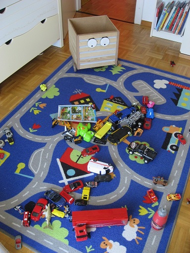
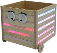
The Ranger is a robot developped at EPFL, at the CHILI and LSRO labs. The project aims at creating a nice, funny robot that would help children to tidy up their rooms.
It is basically a wooden box, with two wheels and animated eyes. It can play sounds and has a large number of LEDs on its faces.
After spending some minutes in the MORSE component library, it appears that the Differential Driver Actuator: Linear and angular speed (V, W) actuator may be a good candidate to control the wheels.
However, for the eyes and the LEDs, we will need to create something new.
But first, we want to create a 3D model of our robot.
Chapter Two: Making a robot mesh
Creating a new robot
Making a new robot model does not require anything beyond creating a 3D mesh in Blender (which also means you can import existing meshes in a variety of formats in Blender).
Note
Creating a realistic robot model may become more complex, especially if you need to use armatures to represent complex kinematic chains, or if you want to create low-poly bounding boxes for good performance when simulating collisions.
In the MORSE data directory (typically, /usr/local/share/morse/data), many 3D
models are available that can be good starting points.
In our case, props/crates.blend contains three models of wooden box that we can
use as starting point.
But first, let’s create a new MORSE project.
Choose a location where you would like to store your simulation, and run:
$ morse create ranger_sim
This creates a new directory called ranger_sim, containing a file called
default.py, and two sub-directories: scripts/, and src/ (initially empty).
The scripts/ directory contains a sample test client; we will return to it in chapter 3.
We can test our simulation immediately:
$ morse run ranger_sim
After MORSE has loaded, it should display something similar to this:
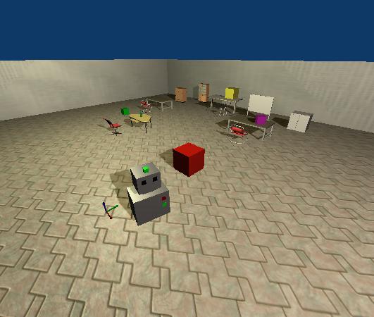
You can already move the robot (Morsy, the MORSE mascot!) with the arrow keys, and if you drive it to an obstacle it should respond to the collision.
Note
You can control the camera by holding down the Ctrl key and moving the mouse, and with the WASD keys.
Let’s now create our own robot model.
First, ask MORSE to create the templates for a new robot called ranger
inside our ranger_sim simulation:
$ morse add robot ranger ranger_sim
This creates several new files in ranger_sim/:
data/ranger_sim/robots/ranger.blend contains a default mesh for our robot,
src/ranger_sim/robots/ranger.py describes the behaviour of our simulated
robot (currently, it does nothing in particular), and
src/ranger_sim/builder/robots/ranger.py describes the Ranger’s equipment,
initially, a simple motion controller and a position sensor.
To use this new robot in our simulation, open ranger_sim/default.py with
your favorite editor, and replace the default robot with the Ranger: add
from ranger_sim.builder.robots import Ranger at the top of the file,
and on line 15 replace Morsy with Ranger. You can also remove
the lines that add the motion controller, the keyboard controller and the pose
sensor since our robot already includes these as part of its default equipment.
The new default.py should look like that:
from morse.builder import *
from ranger_sim.builder.robots import Ranger

robot = Ranger()
robot.translate(1.0, 0.0, 0.0)

robot.add_default_interface('socket')

env = Environment('sandbox', fastmode = False)
env.set_camera_location([10.0, -10.0, 10.0])
env.set_camera_rotation([1.05, 0, 0.78])
Re-run the simulation with:
$ morse run ranger_sim
You should see… no differences! The robot template created by MORSE uses the same mesh as the Morsy robot. We will change that now.
Editing the robot mesh in Blender
Open the Ranger’s current default mesh with Blender:
$ cd ranger_sim
$ blender data/ranger_sim/robots/ranger.blend
Blender opens and should display the Morsy wireframe:
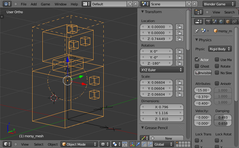
You can press z with the mouse over the 3D view to switch from the wireframe to the solid model.
Now:
- Select all objects (a) and delete them (x)
- Click File > Append, then browse into the MORSE
propsdirectory (typically,/usr/local/share/morse/data/props), and locate and selectcrates.blend - Click on Group, then small_crate, then validate by clicking on the Link/Append from Library button.
- If you do not see the object, check it is not on another layer:

Here, the object has been imported on the third layer. Click it, select everything (a), then move it to first layer (m), and switch back to the first layer.
- Save your file, quit Blender, and relauch the simulation (
$ morse run ranger_sim)
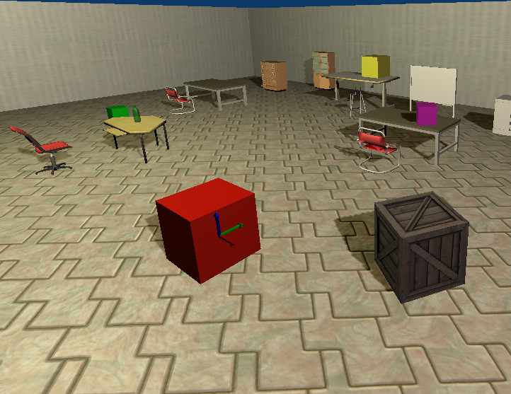
It looks better, but we can improve it even more.
Re-open ranger.blend in Blender and follow these steps:
- Select the crate (right-click on it)
- Switch to Edit mode (Tab)
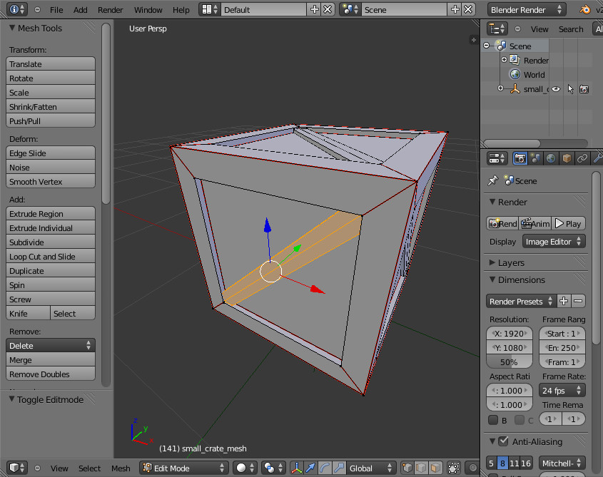
- Remove one by one the diagonal wood boards by selecting one vertex of the board, pressing l to select the connected vertices, and finally x to delete them.
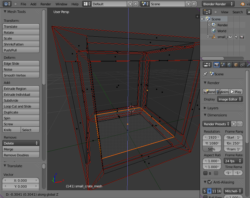
- Still in Edit mode, select the top face…
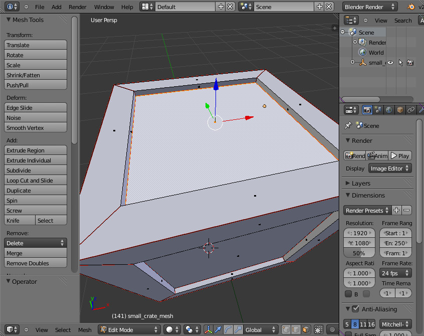
- …and extrude (e followed by z to constrain extrusion in the Z axis) it to create the inner of the box.
- Create the eyes: leave Edit mode (tab), switch to Quad view (menu View > Toggle Quad View), and place the 3D cursor where you want to place the first eye (with a left click)
Warning
In MORSE, the X axis is the forward axis: that is not the Blender convention. You want to add eyes on the Right Ortho face in the Blender interface.
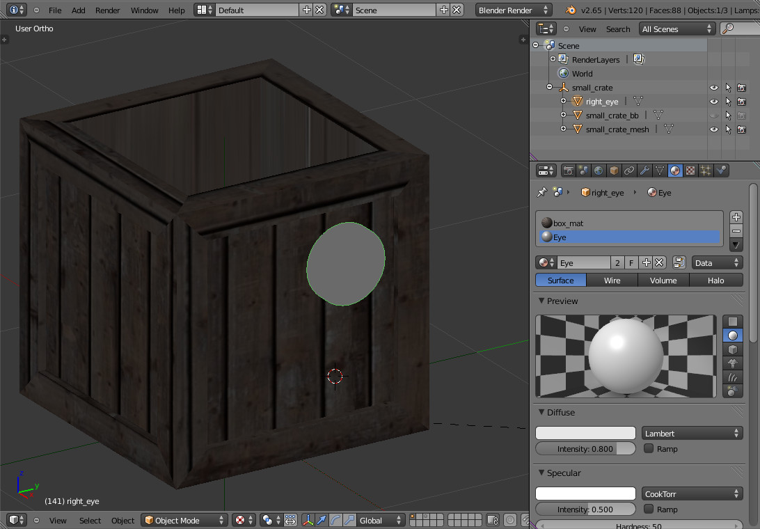
- Add a new cylinder (Shift + a), rotate it by 90 degrees on the Y axis (r y 90 <return>), and scale it (s). Adjust the thickness by scaling again along the X axis (s x). Name your object right_eye (by double-clicking it in the outliner).
- Open the Material panel, create a new material (with the + button), call it Eye. It should be automatically assigned to your object.
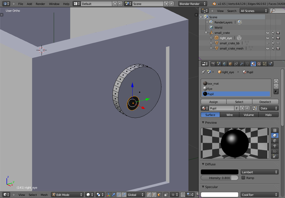
- With the eye selected, switch back to Edit mode. Select all the vertices (a), and duplicate the cylinder (Shift + d). Scale it down and place it to create the pupil. Open the Material panel. Create a new material, name it Pupil, change the Diffuse color to black, and press Assign to assign it to the pupil vertices.
- Leave Edit mode and apply the scale transformation: Ctrl + a, then Scale. Duplicate the eye (Shift + d) and move it along the Y axis (g y).
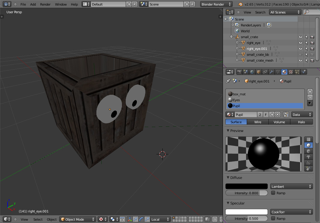
Save you file, quit Blender, and run your simulation: that should be enough to start playing around a bit!
In the next chapter, we’ll see how to control the robot’s movement from an external application (your robot controller), and in the following chapter, we will try to move the eyes (we will have to create a new dedicated actuator to achieve this).
Chapter Three: Our first robot controller
MORSE is all about integrating simulation as transparently as possible in your usual workflow: we want you to be able to switch almost transparently from a real robot to the simulated robot.
To achieve this, MORSE relies on intermediate middlewares, like ROS, YARP, etc. You can get an idea of which features of which middlewares are supported by MORSE on this page.
Sometimes, for quick prototyping, or simply to evaluate what it is actually possible to simulate, you do not want to use a full middleware, but a more lightweight interface. MORSE comes with a simple socket-based interface for that purpose, and also a simple-to-use Python binding that will enable us to quickly test our robot controller.
Moving the robot
Let write a first test right away. Open your favorite editor and copy and paste this example:
1 2 3 4 5 6 7 8 9 10 11 12 13 14 15 16 17 18 19 20 21 22 23 24 25 26 | from pymorse import Morse
print("Use WASD to control the Ranger")
with Morse() as simu:
motion = simu.robot.motion
v = 0.0
w = 0.0
while True:
key = input("WASD?")
if key.lower() == "w":
v += 0.1
elif key.lower() == "s":
v -= 0.1
elif key.lower() == "a":
w += 0.1
elif key.lower() == "d":
w -= 0.1
else:
continue
motion.publish({"v": v, "w": w})
|
Save it somewhere (for instance, as ranger_sim/scripts/keyboard_ctrl.py),
launch the simulation ($ morse run ranger_sim), and run your script:
$ morse run ranger_sim &
$ python3 ranger_sim/scripts/keyboard_ctrl.py
Note
A client script, very similar to this one, is automatically generated when creating the
simulation environment. You will find it under
scripts/ranger_sim_client.py.
Warning
pymorse the Python bindings for MORSE, require Python 3
Press Ctrl + c to interrupt the keyboard_ctrl.py script.
Now let’s examine this first example in detail.
On line 1, we import the pymorse bindings. To use them, on line 5 we create
a context: on entering the context, the connection is established with the simulator (by
default, on localhost, but you can change this),
and when we exit the context, the connections are properly closed. In this
example, the context object is stored in the simu variable.
On line 7, we retrieve the motion controller end-point. The name used to access
it is the same as how we named our components in the simulation script
(default.py and ranger.py).
Note
Here, in default.py, on line 5, we called our robot robot by simply
using that name when creating the Ranger() object:
1 2 3 4 5 6 7 8 9 10 11 | from morse.builder import *
from robots import Ranger
robot = Ranger()
# The list of the main methods to manipulate your components
# is here: http://www.openrobots.org/morse/doc/stable/user/builder_overview.html
robot.translate(1.0, 0.0, 0.0)
[...]
|
If you check src/ranger_sim/builder/robots/ranger.py, you will find that
the Ranger’s motion controller has been called motion. So with
pymorse, we access the motion controller simply as
simu.robot.motion.
Then, at line 12, we start the main loop: we read a keyboard input, we change the
linear v and radial w speeds depending on the user input, and,
in line 26, we send the simulator the new command.
The command is a plain Python dictionary, whose content depends on the
actuator. In our case, we are using a MotionVW actuator (see
src/ranger_sim/builder/robots/ranger.py). The documentation of the
component tells us what the actuator expects.
Accessing sensors
motion is an actuator. If you open robots/ranger.py, you will see the
template also declare a Pose sensor. We can access it
to print the robot’s current position. Open scripts/keyboard_ctrl.py
and modify it as follows:
1 2 3 4 5 6 7 8 9 10 11 12 13 14 15 16 17 18 19 20 21 22 23 24 25 26 27 28 29 30 31 | from pymorse import Morse
def pose_received(pose):
print("The Ranger is currently at %s" % pose)
print("Use WASD to control the Ranger")
with Morse() as simu:
simu.robot.pose.subscribe(pose_received)
motion = simu.robot.motion
v = 0.0
w = 0.0
while True:
key = input("WASD?")
if key.lower() == "w":
v += 0.1
elif key.lower() == "s":
v -= 0.1
elif key.lower() == "a":
w += 0.1
elif key.lower() == "d":
w -= 0.1
else:
continue
motion.publish({"v": v, "w": w})
|
Restart the scripts/keyboard_ctrl.py script:
$ python3 ranger_sim/scripts/keyboard_ctrl.py
It should start quickly filling your console with the robot’s position. You can still control it with WASD as you did previously, and you should see the position values changing.
Chapter Four: Creating a new actuator to move the eyes
A First Skeleton
Let’s now create a new custom actuator for the robot’s eyes.
Add a new actuator template called
eyesto theranger_simsimulation:$ morse add actuator eyes ranger_sim
MORSE asks you for a short description of your actuator (enter something like
“Controls the eyes of the EPFL Ranger robot”) , and then create a new set of
templates: src/actuators/eyes.py defines the behaviour of the actuator (how
the actuator interacts with the simulation), and
src/builder/actuators/eyes.py provides the Builder API interface to use
the actuator in simulation scripts.
Note
Unlike with robots, where you are encouraged to modify their Builder API to define the robot equipment, you usually do not need to change it for actuators or sensors.
The only case where it may be useful is to specify a special 3D mesh for your component (like the casing of a laser scanner, etc.)
The default actuator template does not provide any useful behaviour, but it can already be added to our robot:
- Open
src/ranger_sim/builder/robots/ranger.py, and add thisimportstatement:
from ranger_sim.builder.actuators import Eyes
and these two lines after the motion controller:
self.eyes = Eyes()
self.append(self.eyes)
If you launch the simulation now, MORSE will list the components available on our robot, including the eyes:
[...]

[    0.283] ------------------------------------
[    0.284] -        SIMULATION SUMMARY        -
[    0.284] ------------------------------------
[    0.284] Robots in the simulation:
[    0.284]     ROBOT: 'robot'
[    0.284]         - Component: 'robot.pose'
[    0.285]         - Component: 'robot.keyboard'
[    0.285]         - Component: 'robot.eyes'
[    0.285]         - Component: 'robot.motion'

[...]
Moving the eyes
For our actuator to produce something tangible, we need to complete its definition.
Open src/ranger_sim/actuators/eyes.py, and update its content to match the
following Python script:
1 2 3 4 5 6 7 8 9 10 11 12 13 14 15 16 17 18 19 20 21 22 23 24 25 26 27 28 29 30 | import logging; logger = logging.getLogger("morse." + __name__)
from morse.core.actuator import Actuator
from morse.helpers.components import add_data
from morse.core import mathutils
class Eyes(Actuator):
    _name = "Eyes"
    _short_desc = "Controls the eyes of the EPFL Ranger robot"
add_data('left', 0.1, 'float', 'Left eye rotation, in radians')
add_data('right', -0.1, 'float', 'Right eye rotation, in radians')
def __init__(self, obj, parent=None):
      logger.info("%s initialization" % obj.name)
      # Call the constructor of the parent class
      Actuator.__init__(self, obj, parent)

      self.left_eye = parent.bge_object.children["left_eye"]
      self.right_eye = parent.bge_object.children["right_eye"]

      logger.info('Component initialized')
def default_action(self):

      l_orientation = mathutils.Euler([self.local_data['left'], 0.0, 0.0])
      self.left_eye.orientation = l_orientation.to_matrix()

      r_orientation = mathutils.Euler([self.local_data['right'], 0.0, 0.0])
      self.right_eye.orientation = r_orientation.to_matrix()
|
Let’s explain this script:
class Eyes(Actuator):
_name = "Eyes"
_short_desc = "Controls the eyes of the EPFL Ranger robot"
When creating a component, always provide a name and short description. These are used to generate the component documentation for instance.
add_data('left', 0.1, 'float', 'Left eye rotation, in radians')
add_data('right', -0.1, 'float', 'Right eye rotation, in radians')
These two lines define the data interface of our actuator. For the eyes, we need to provide to the actuator with two angles, one per eye.
We first set the name of the data field, then its default value, its type and a short description.
The data set by the simulator clients can be later accessed through the
local_data dictionary (see below).
def __init__(self, obj, parent=None):
logger.info("%s initialization" % obj.name)
# Call the constructor of the parent class
Actuator.__init__(self, obj, parent)
self.left_eye = parent.bge_object.children["left_eye"]
self.right_eye = parent.bge_object.children["right_eye"]
logger.info('Component initialized')
The class constructor has nothing special. self.left_eye and
self.right_eye are set to point to the Blender objects for the eyes
(parent is the robot body, parent.bge_object represents the Blender
mesh of the robot body, parent.bge_object.children contains all the
robot mesh’s children).
def default_action(self):
l_orientation = mathutils.Euler([self.local_data['left'], 0.0, 0.0])
self.left_eye.orientation = l_orientation.to_matrix()
r_orientation = mathutils.Euler([self.local_data['right'], 0.0, 0.0])
self.right_eye.orientation = r_orientation.to_matrix()
default_action() is a component’s most important method. It is
called at each simulation step. The behaviour of the actuator is implemented
here.
For our eyes, we simply apply a rotation along the X axis (Blender uses
rotation matrices, so we first create the rotation matrix from a vector of
Euler angles).
To test the eyes, we must complete our test client.
Re-open scripts/keyboard_ctrl.py, and change it to this:
from pymorse import Morse

print("Use WASD to control the Ranger")

with Morse() as simu:

    motion = simu.robot.motion
    eyes = simu.robot.eyes

    v = 0.0
    w = 0.0

    left = 0.0
    right = 0.0

    while True:
        key = input("WASD (eyes:RFTG)?")

        if key.lower() == "w":
            v += 0.1
        elif key.lower() == "s":
            v -= 0.1
        elif key.lower() == "a":
            w += 0.1
        elif key.lower() == "d":
            w -= 0.1

        elif key.lower() == "r":
            left += 0.1
        elif key.lower() == "f":
            left -= 0.1
        elif key.lower() == "t":
            right += 0.1
        elif key.lower() == "g":
            right -= 0.1

        else:
            continue

        motion.publish({"v": v, "w": w})
        eyes.publish({"left": left, "right": right})
Besides (v, w), we now also publish on the eyes channel a pair (left, right).
Run the simulation and launch your client:
$ morse run ranger_sim &
$ python3 ranger_sim/scripts/keyboard_ctrl.py
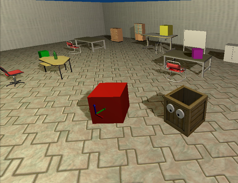
You should now be able to move the eyes:
Chapter Five - The simulation environment
To be done!
Chapter Six - Creating an advanced actuator: the LED arrays
To be done!