Armatures creation
Armatures are the MORSE way to simulate kinematic chains made of a combination of revolute joints (hinge) and prismatic joints (slider).
They are based on Blender’s armatures. You may want to read some background information about them before creating our own rig: How armatures work?, Armature documentation.
Note
To make the vocabulary clear: Kinematic chains are what Blender calls armatures. Armatures are made of bones. The pose of a bone is stored as the bone’s pose channel. A bone is both a joint and the rigid segment attached to it. We often use the term joint (in the documentation and in MORSE code) either for a bone or its channel.
Warning
Currently, armatures in MORSE have one notable constraint: each of the joints of the armature must have at most one Degree of Freedom (DoF). If you need to model a linkage with two or more degrees of freedom, add one joint per DoF.
Since joints in Blender’s armatures can not have a zero-length, it is currently not possible to represent two DoF with the same origin.
Please refer to issue 382 to learn more about this problem and possible workarounds.
In addition, the Blender armature needs some special configuration, detailed below.
Creating armatures
The following procedure should help you to create Blender armatures suitable for simulation. It assumes you already have a correct mesh for your system (one independent Blender object for each rigid body).
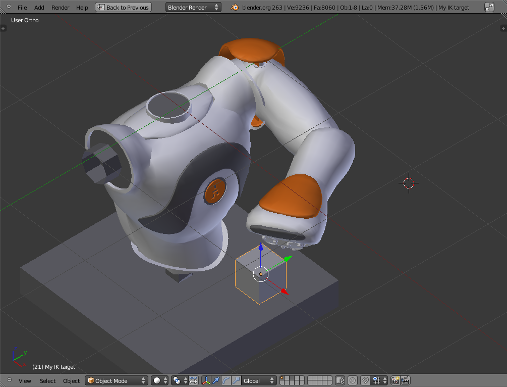
As an example, we will walkthrough the creation of an armature for the left arm of Nao.
- Snap the 3D cursor to the center of the armature origin (for Nao, the center
of the chest, select the chest, then press : kbd:space and type
Snap
cursor to active
) - Add armature (Shift+A >
Armature) - Snap the 3D cursor to the center of the rigid body at the end of the link (for instance, select the shoulder mesh, and snap the 3D cursor to the center of this mesh)
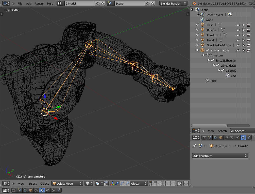
- Select the last bone of the armature, switch to Edit Mode (Tab),
select the head, snap the selection to the 3D cursor (space and
Snap
selection to cursor
). This places the bone correctly between the two rigid bodies. Rename the bone using the formBodyA2BodyB(for instance,Torso2LShoulder) - Extrude the bone (E)
- Repeat steps 3, 4 and 5 until the armature is complete
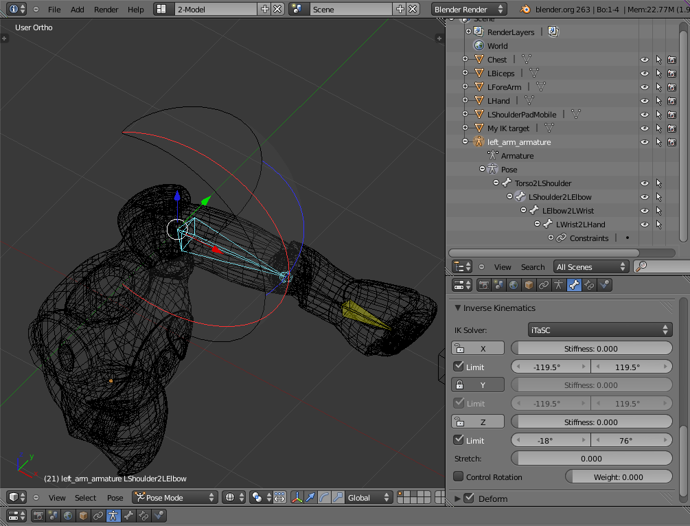
- Select the armature, switch to Pose Mode, select the last bone, add a Bone Constraints of type Inverse Kinematics. Check the Stretch option if you have slider joints in the kinematic chain.
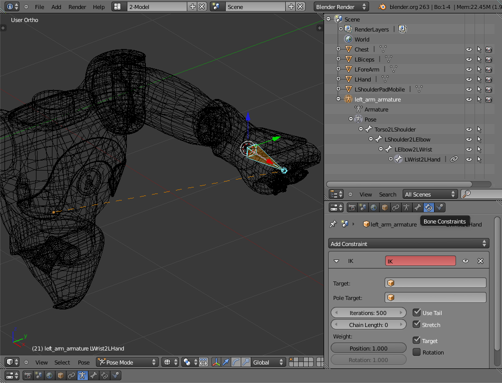
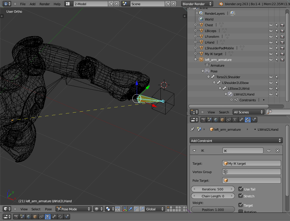
- Create a new mesh (like a cube) to serve as IK target, and set it accordingly in the Bone Constraints panel of the last bone. Now, if you move your IK target, you should see the whole armature moving accordingly.
Note
You do not need to keep the IK targets or manually create IK targets for each of the kinematic chains since they can conveniently be added in your Builder script. See the documentation of the Armature actuator for details.
- For each of your bones, set the correct IK limits from their Bone > Inverse Kinematics menu. Select the enabled rotation axis and the rotation limits. If the joint is a slider (i.e., a translation), use the Stretch value to set the maximum translation allowed, in meters (in that case, you must use the Legacy IK solver). Setting rotation limits should lead to a nice 3D display of reachable positions for the joint.
- Parent meshes to bones: select the mesh, then select the bone you want to be attached to the mesh, then add the armature to the selection (Shift+click the armature), then Ctrl+P and select Set parent to… Bone. Repeat this step for each bone.
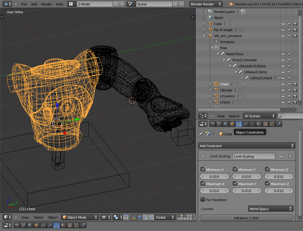
- If necessary, use Object Constraints (like Limit scale or Limit rotation) on meshes to get the expected behaviour (for instance, to prevent scaling when the Stretch IK limit is used, or when a mesh can only rotate on one axis of a multi-DoF joint).
Setting the joints tags
If objects are intended to get connected to your armature (typically, an arm
grasping something), you need to mark all Blender objects belonging to your
model as internal and to mark one object as the end effector (the slot
where other objects will be appended).
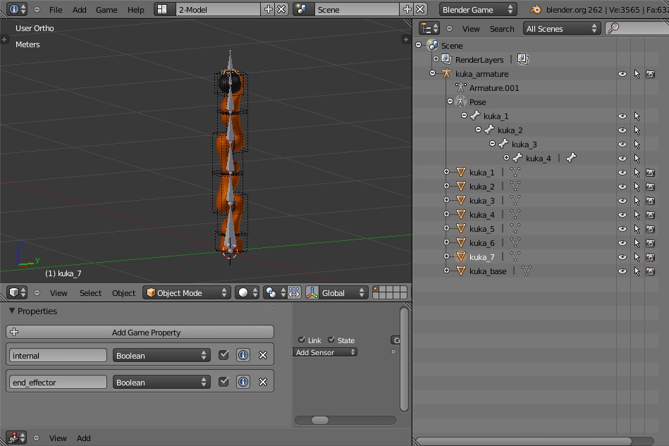
Use game properties (as shown in the screenshot above) to mark these properties.
Note
This step is not mandatory if your armature is not intended to support objects appending.